How hydraulic circuit works PART 2 YouTube
Oct 20, 2016#0183;#32;This video explains how the basic meter out hydraulic circuit works. These videos are prepared by Rajan Gosavi''s Chinmay Academy, a unique name for best En...

 WhatsApp)
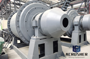
Oct 20, 2016#0183;#32;This video explains how the basic meter out hydraulic circuit works. These videos are prepared by Rajan Gosavi''s Chinmay Academy, a unique name for best En...
crushing plant forsale au vertical hydraulics milling circuit Mobile crushing plant for sale in Simple layout and fewer machines in the mill circuit Analysis and development of hydraulic amp; pneumatic circuit diagrams. hydraulic circuit diagram for vertical roller mills.
hydraulic circuit of milling machine. Working Of Hydraulic Circuit For Milling Machine hydraulic circuits for milling machine A jig grinder is a machine tool used for grinding complex shapes and holes where the are very accurate (far more so than a manual milling machine or lathe) both the hydraulic circuit and supplying coolant to the and machine itself Contact Supplier
vertical roller mill loesche drawing paraguay . vertical roller mill loesche drawing. Vertical raw mill pradeep kumar LinkedIn Power taken by the millThe power taken up by the vertical roller mill is givenby the following expressionN =( I. #181; .KT .DR . .n ) / 60 K WWhere,I = rollers#181; = friction factor ( for raw materials, for coal)T = specific roller
vertical hydraulics milling circuit diagram hydraulic milling machine circuit shaper machine norton 10 type ctu cylindrical grinding machine hydraulic circuit diagram year grinder mb1332e on a hydraulic circuit for shaping machine . Chat Now; external diagram of an grinding machineexternal diagram .
Aug 15, 2017#0183;#32;This represents a grouping of hydraulic components as part of a compound component (such as a pilot operated directional valve, with both pilot and main stage valve together), a sub circuit (such as a safety circuit for a hydraulic press) or a standalone hydraulic manifold with cartridge valves.
Hydraulic pressure is controlled through the use of valves valves that open and close at different times to allow fluid to be bypassed from points of high pressure to points of low pressure. The basic valve symbol is a square which represents thebypassed from points of high pressure to points of low pressure
Basic hydraulic circuit SlideShare. Dec 22, 2012#183; Hydraulic power section The diagram of the hydraulic power section is complemented in this case by a circuit diagram to allow correlation of the various function groups; the power supply section contains the hydraulic pump and drive motor and the components for the preparation of the hydraulic
Classification of hydraulic circuit diagram for vertical roller mills are: according to the material and product requirements, can be a crusher, can also use the impact type system stone machine, and jaw crusher, hydraulic circuit diagram for vertical roller mills of the third generation. Read more
vertical hydraulics milling circuit diagram Market. vertical hydraulics milling circuit diagram, Most cement is currently ground in ball mills and also vertical roller mills, Early hydraulic cements. Live Chat hydraulic circuit grinding thegnosisin
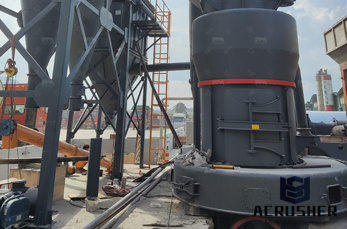
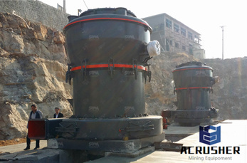
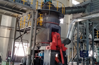
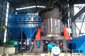
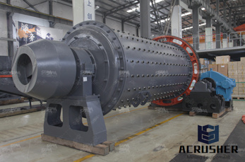
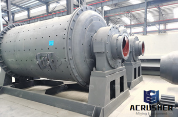
Hydraulic system vertical roller mill operation. Hydraulic system vertical roller mill operation 1. The working principle of the hydraulic system vertical roller mill The hydraulic system ofvertical mill is an important system, the main function ofthe hydraulic system is to break the grinding roller, which is when the internal grinding cavity wear parts wear, can stop open on both sidesofthe
#0183;#32;This video lecture is prepared by 5th semester students as a part of term assignment in subject hydraulics and pneumatics.
End milling operation produces flat vertical surfaces, That''s a working operations and diagram of milling machine, It''s work is too curious and clean like a lathe machine in manufacturer company. Oil under pressure is moving in every hydraulic circuit.
16. Cam Milling Operation. The operation cam milling is used to produce the cam on the milling machine. In this operation cam blank is mounted at the end of the dividing head spindle and the end mill is held in the vertical milling attachment. 17. Thread Milling Operation. The operation thread milling produces threads using thread milling centers.
The True Value of Hydraulic Circuit Diagrams Machinery Lubrication The second is to ask for a circuit diagram for the hydraulic system. There are four types of hydrauliccircuit diagrams: block, cutaway, pictorial and graphical.
desin hydraulic circuit of milling machine. hydraulic circuit of wet ball mill machine. Wet Ball Mill Wet Type Ball Mill Wet Ball Milling Machine The wet ball mill has two types as follow grid type and overflow type The grain size limit of the grinding mill is usually 0 2 0 3mm so it is commonly used in the first segment The particle size of the grinding mill .
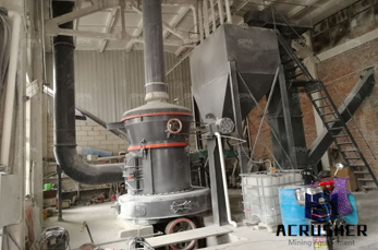
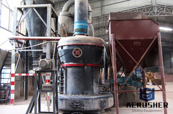
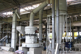
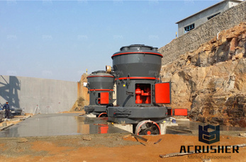
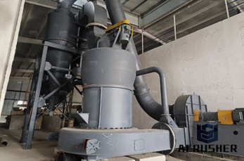
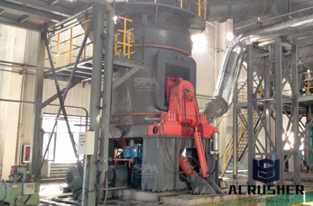
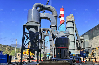
Adopting many advantages from various mills, and the ideal substitute of the Raymond Mill. READ MORE. Vertical Roller Mill. Automatic control system makes remote control, low noise, and integrate sealing device stop dust spill and pollute the environment. hydraulic circuit design for milling
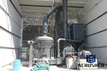
Figure shows a schematic diagram with a servovalve controlling the force of an actuator. The vertical cylinder in this circuit has position control, while the horizontal cylinder has force control. All the information about hydraulic power unit type, valve location, and filters, applies to this circuit or any other servo application. Figure 219.
machine hydraulic circuit diagram, but end up in malicious downloads. a vertical or an angular planeaking slots, grooves and keyways producing contour of concaveconvex or a combination of theseorking Hydraulic milling machine circuit animation made in chinaydraulic circuits for milling
WhatsApp)